
STM32F103C6T6/STM32F103C8T6 ARM STM32 Minimum System Development Board Module
- $1.17 / >=2 pieces
- 2 pieces
- Shenzhen Tengwei Electronic Technology Co., Ltd.
- Guangdong, China
- Mr Mark Lin
PRODUCT DETAIL
| Sales unit: | single product | type: | development board |
| brand: | Tengwei | model: | STM32 minimum system development board |
| Single package size: | 5X3X2 cm | Origin: | Guangdong, China |
| IC/parts used: | China IC | Gross weight per piece: | 0.010 kg |
Product Description
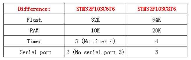
STM32F103C8T6 is different from STM32F103C6T6
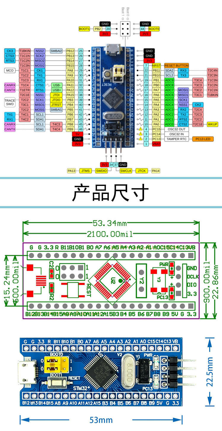
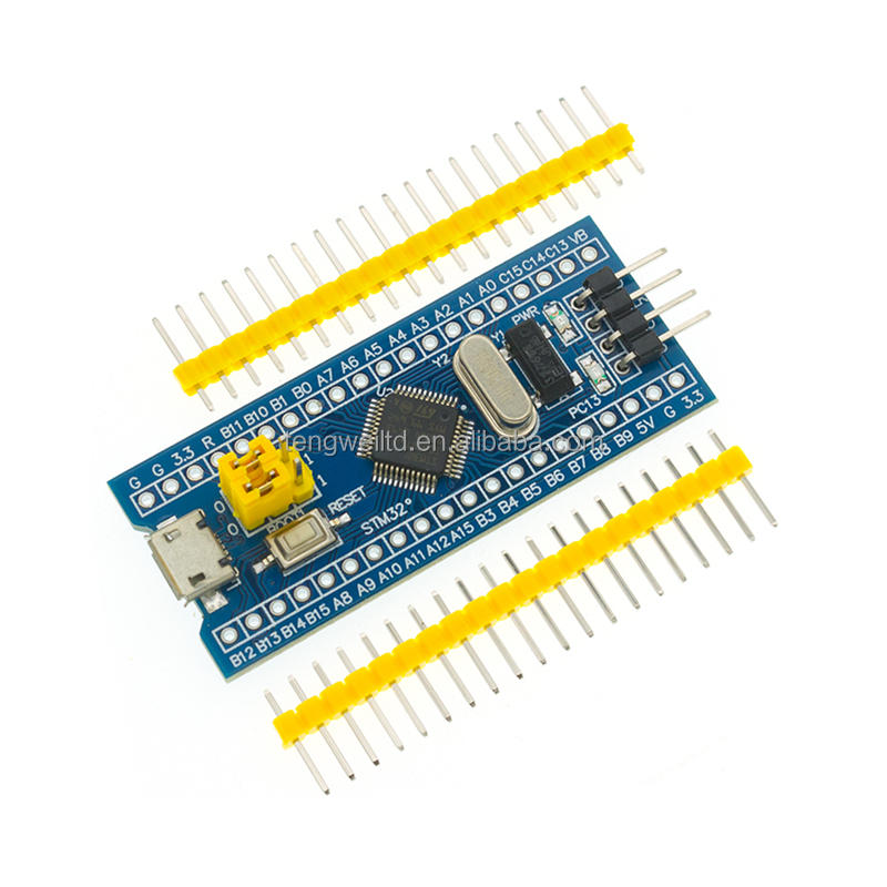
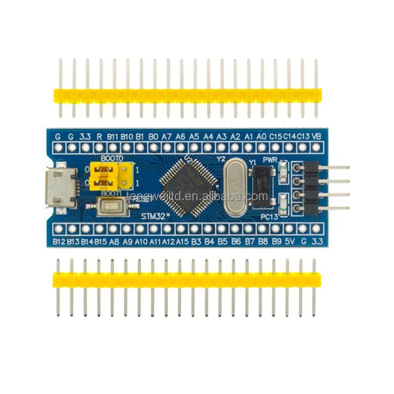
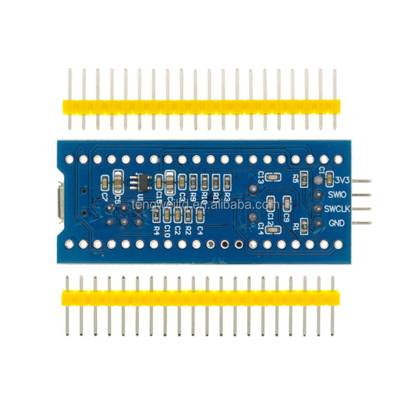
This is a core chip based on the CS32F103C8T6 ARM core board. The features are as follows: 1. The board is based on the most basic MCU circuit, 8M and 32768 crystal oscillator circuit, and USB power supply circuit. 2. The core board is divided into two rows leading to all I/O ports. 3. With SWD simulation debugging download interface, it is simple and convenient, and the debugging speed is fast. 4. Using the Mirco USB interface, it can be used for USB communication and power supply. The USB interface is compatible with ordinary Android mobile phone charger interfaces. 6. RTC crystal oscillator Epson brand, easy to start, more stable. 7. It has double headers, but the headers are not welded by default. Users can choose the welding direction that suits them according to their own application scenarios. If welding is required, please inform the owner. It can be compiled with Keil, compiled with IAR, and the program can be downloaded through J-Link or USART1. The program has a host and a debugging program. If you have any questions, you can consult the host.
Chip description: 1. 32F103C8T6 Package type: LQFP; Number of pins: 48; Core: Cortex-M3; Operating frequency: 72MHz; Storage resources: 64K Byte Flash, 20KByte SRAM; Interface resources: 2x SPI, 3x USART, 2x I2C, 1x CAN, 37x I/O ports, analog-to-digital conversion: 2x ADC (12-bit/16-channel) Timer: 3 general-purpose timers and 1 advanced timer Debug download: Support JTAG/SWD debug interface download, support IAP. 2. RT9193: 3.3V regulator chip with a maximum output of 300mA.
Interface description: 1. SWD interface: supports simulation, download and debugging. 2. Mirco USB interface: power supply and USB communication, does not support downloading. 3. USART1 interface: USART1 can be used to download programs, and USART1 can also be used for communication. 4. MCU pin interface: lead out all I/O port pins for easy connection with peripherals. 5. 5V and 3.3V power input and output interfaces: often used for external power supply, or common ground processing with other modules
Other equipment instructions: 1. Power indicator light (PWR): The status of the power indicator light can judge whether the power supply is stable. 2. User LED (PC13): convenient for I/O output testing or indicating program operation. 3. Start to jump to select the programming mode: (1, user flash memory 2, SRAM 3, system memory). 4. Reset key: reset the chip for the user program. 5. 8M crystal oscillator: the frequency can be set to make the system clock frequency 72MHz. 6,32.768KHz Crystal: Can be used for built-in RTC, or for calibration.
VIEW MORE
YOU MAY LIKE
Other Products
-
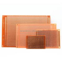 Printed circuit board 5X7/7X9/9X15/12X18cm single-sided PC board DIY experimental general board breadboard 2.54mm PCB$0.02 / piece
 -
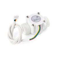 Water Flow Sensor YF-S403 Flowmeter S403 Hall Flow Sensor 3/4 Inch Water Control Fluid Flow Sensor Switch$2.00 / piece
 -
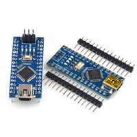 ATMEGA328P NANO V3.0 Development Board with ATMEGA328PB Mini Microcontroller Module For arduino nano$0.18 / piece
 -
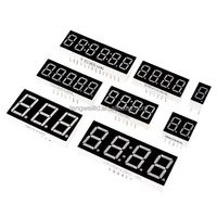 0.56" 7-segment 4-digit LED display 0.56" red 4 characters$0.18 / piece
 -
 2.54mm Connector 1*20 Pin Straight Male Connector Header 20 Pin Right Angle 20 Position 1 Row$0.025 / piece