ME131M ME131S multi-circuit multi-sensor current monitoring meter
- $158.00 / 1 - 9 pieces
$128.00 / 10 - 99 pieces
$98.00 / 100 - 499 pieces
$68.00 / >=500 pieces - 1 piece
- Shanghai Pinyan M&C Technology Co., Ltd.
- Shanghai, China
- Mr Ben Yan
PRODUCT DETAIL
| application: | Energy consumption monitoring | voltage range: | 0-600VAC |
| Current Transformer: | 333mV CT | Operating temperature: | -25℃~+60℃ |
| Current range: | 0-10000A | level of accuracy: | 0.5S level |
| Sales unit: | Single product | Gross weight of single piece: | 3.000kg |
| Measuring voltage range: | 0~600VAC | frequency: | 45~60 Hz |
| Measuring current range: | 0-10000A | Product Category: | DIN RAIL multi-loop power meter |
| current sensor: | Rogowski coil current clamp | Package preview: | |
| Packaging details: | 1 set/box optional Rogowski coil sensor: 100A MRC-24 600A TRC-36 1000A NRC-100 3000A NRC-150 6000A NRC-200 | Place of origin: | China Shanghai |
| model: | ME131 | aspect: | ME131M: 9.3*8.0*3.6cm; ME131S: 9.3*8.0*1.81cm |
| communicate: | Modbus RTU, RS485 | brand: | Metro |
| Single piece packaging size: | 25X25X20cm | Function: | Measure multiple circuit currents |
| product name: | Three-phase multi-circuit power meter |


Product Description
DIN RAIL multi-channel smart energy meter
ME131
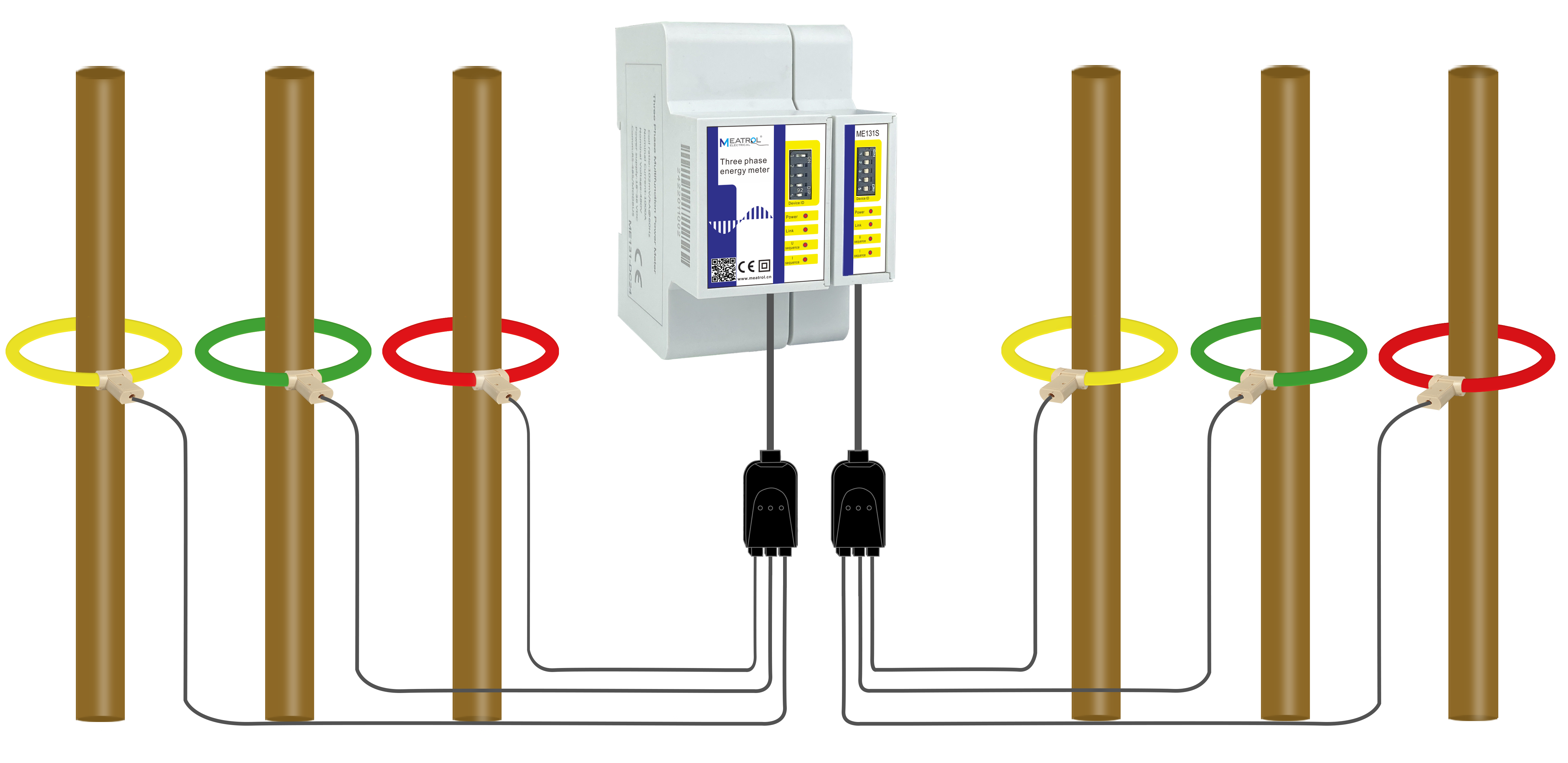
ME131Multi-channel smart energy meters are compatible with Rogowski coils and voltage output split-core current transformers, which can realize wire removal-free testing, simplify testing procedures, and save construction costs.
ME131 multi-channel smart energy meter supports three-phase three-wire system and three-phase four-wire system. It can measure various electrical parameters such as current, voltage, power factor, harmonics, power, and electric energy of the L1, L2, and L3 phases of the power grid. ME131 comes standard with RS485 communication interface and standard Modbus-RTU protocol, is compatible with various configuration systems, and can transmit electrical parameters collected by the front end to the system data center in real time.
ME131 multi-circuit smart energy meter | ||
describe | ||
Installation type | DIN rail | |
model. | Chief Accountant:ME131M Sub-table:ME131S | |
Current sensor type | Rogowski coil Voltage output current transformer | |
feature | Direct connection to Rogowski coil | |
Advantage | Wide current range, no need to disassemble the measurement | |
Wiring system | 3P4W_3CT, 3P3W_3CT, 3P3W_2CT, 1P3W, 1P2W | |
Application areas | Power analysis and energy consumption monitoring | |
Display | not any | |
weight | ME131M: 122 grams ME131S: 59 grams | |
size | ME131M: length*width*depth 9.3*8.0*3.6CM; ME131S: length*width*depth 9.3*8.0*1.81CM | |
Channel input voltage range | 0-900mVAC peak, 636 mV RMS | |
Measuring range | Different current sensors have different measurement ranges | |
Rogowski coil | 50mV/kA@50Hz(0-12000A),@60Hz(0-10000A) 85mV/kA@50Hz(0-7000A),@60Hz(0-6000A) 100mV/kA@50Hz(0-6000A),@60Hz(0-5000A) ... | |
Voltage output CT | 0~99999A | |
Measuring range | 0~600VAC | |
Switching output (digital signal) | 1 electromagnetic relay output, contact capacity: 3A 30V DC, 3A 250V AC | |
Switch input (digital signal) | Optocoupler isolation (5kVrms) | |
RS485 communication | 1 RS485 communication interface Interface type: two-wire half-duplex Communication baud rate: 2400bps~38400bps Protocol: Modbus-RTU | |
power supply | 85~265VAC/110~370VDC, 45~60Hz (24V DC power supply version can be customized) | |
Maximum power consumption | ≤3.5VA | |
Measurement parameters | ||
instantaneous value | ||
phase voltage | U1, U2, U3, AVG, U0 (zero sequence voltage) | |
Line voltage | U12, U23, U31, average | |
current | I1, I2, I3, average, input | |
Grid frequency | F1, F2, F3, Σ | |
Power factor PF | PF1, PF2, PF3, Σ | |
Fundamental power factor DPF | DPF1, DPF2, DPF3, Σ | |
Active power | P1, P2, P3, Σ | |
Reactive power | Q1, Q2, Q3, Σ | |
inspecting power | S1, S2, S3, Σ | |
vitality | ||
active energy location | EP1, EP2, EP3, Σ | |
negative active energy | EP1, EP2, EP3, Σ | |
Reactive energy location | EQ1, EQ2, EQ3, Σ | |
Reactive energy Neg. | EQ1, EQ2, EQ3, Σ | |
apparent energy | ES1, ES2, ES3, Σ | |
tariff energy | ET1, ET2, ET3, ET4, ET5, ET6 | |
harmonic | ||
Voltage harmonic distortion | Total harmonics (U1, U2, U3) Odd total harmonics (U1, U2, U3) Even-order total harmonics (U1, U2, U3) 1-50th harmonic (U1, U2, U3) | |
Current harmonic distortion | Total harmonics (I1, I2, I3) Odd total harmonics (I1, I2, I3) Even-order total harmonics (I1, I2, I3) K coefficient (I1, I2, I3) 1-50th harmonic (I1, I2, I3) | |
Voltage harmonic value | Total harmonics (U1, U2, U3) 1-50th harmonic (U1, U2, U3) | |
Current harmonic value | Total harmonics (I1, I2, I3) 1-50th harmonic (I1, I2, I3) | |
stage | ||
phase sequence | Voltage and current | |
voltage angle | U1, U2, U3 | |
current angle | I1, I2, I3 | |
voltage current angle | User Interface 1, User Interface 2, User Interface 3 | |
Require | Total active power, total reactive power, total apparent power | |
Total active power maximum demand | Maximum demand and time | |
Total reactive power maximum demand | Maximum demand and time | |
Maximum demand for total apparent power | Maximum demand and time | |
Voltage imbalance | Negative sequence, zero sequence | |
Current imbalance | Negative sequence, zero sequence | |
maximum. & minimum. | ||
phase voltage | Each phase and average | |
Line voltage | Each phase and average | |
current | Each phase and average | |
Active power | Each stage and total | |
Reactive power | Each stage and total | |
inspecting power | Each stage and total | |
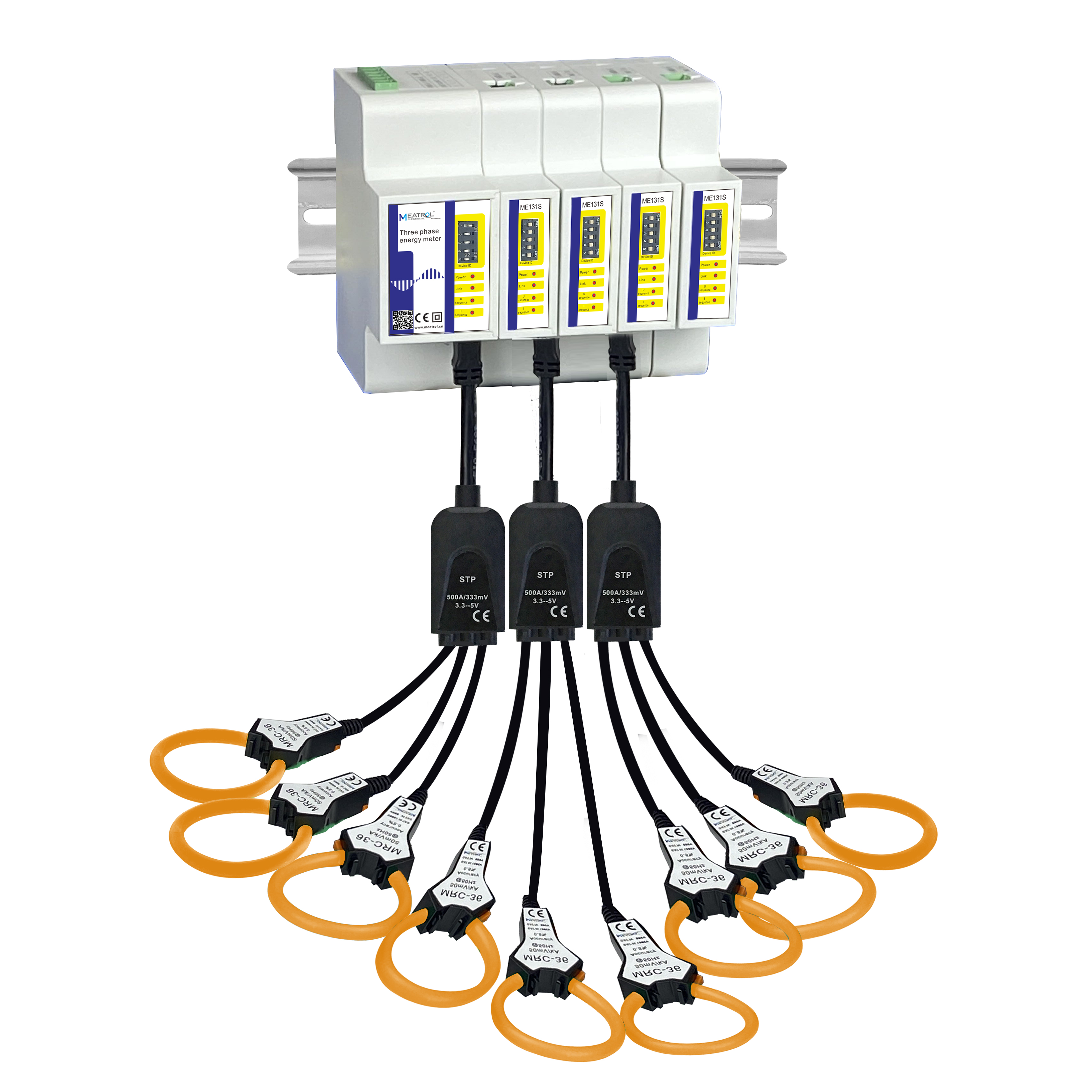
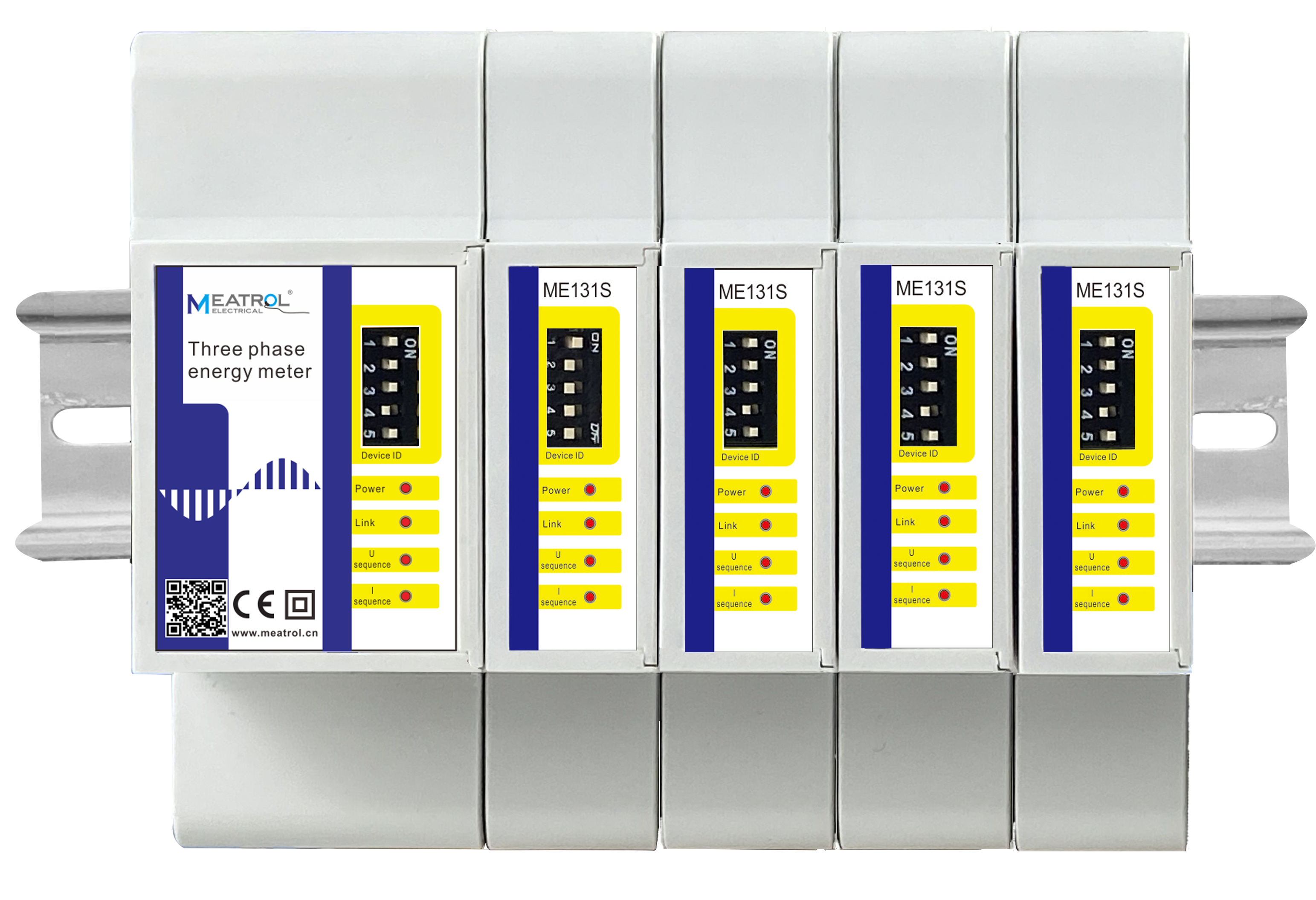
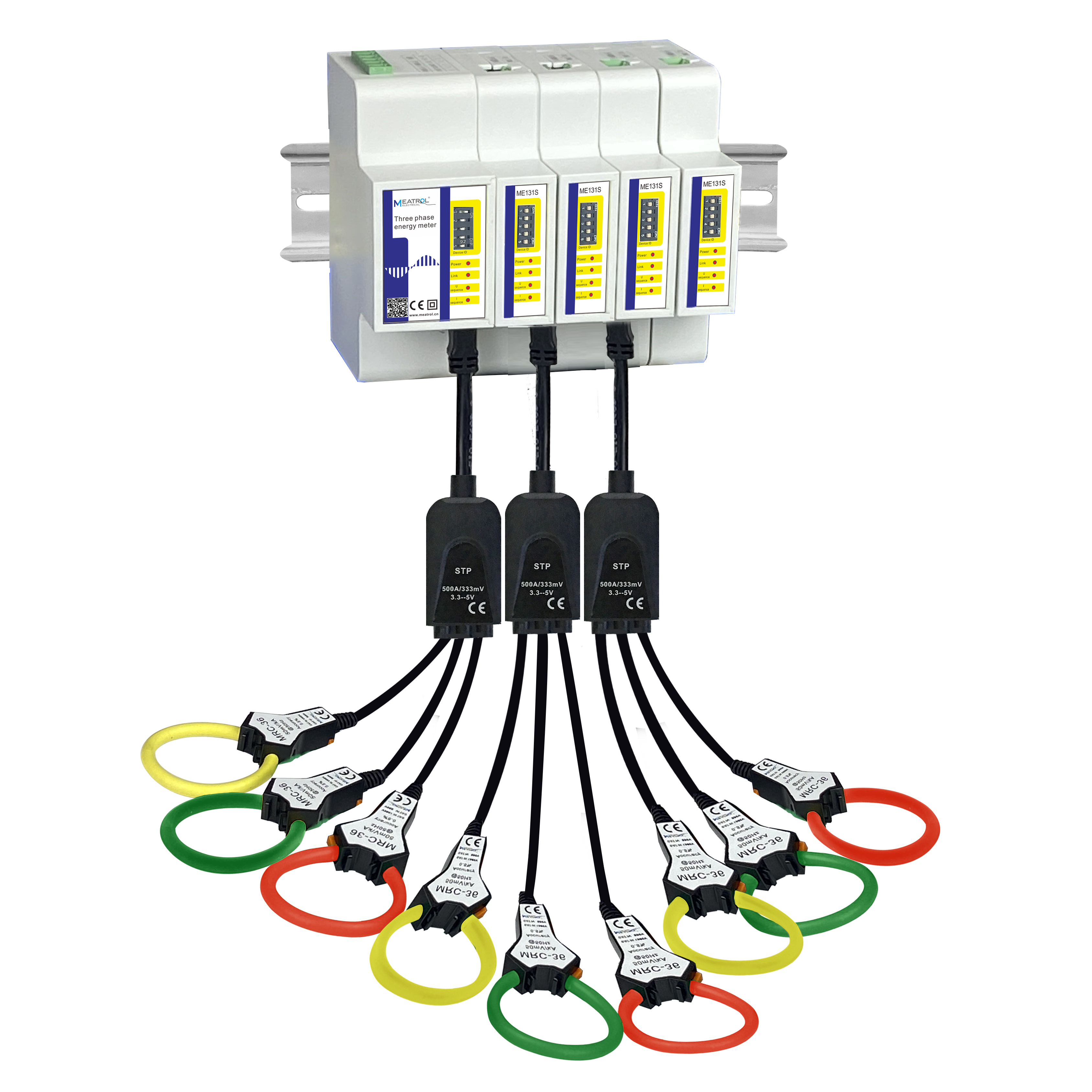
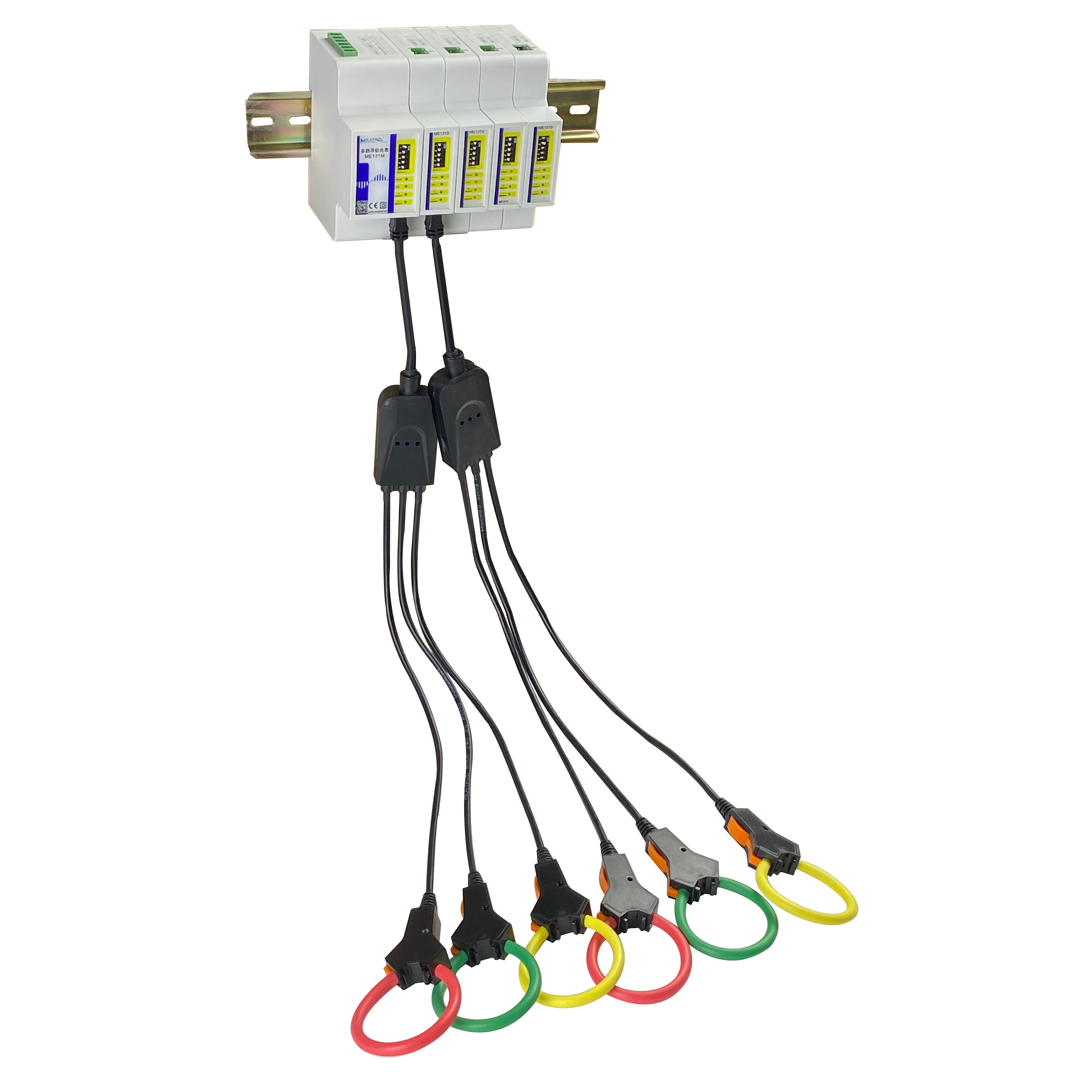
Centralized installation, compact and space-saving
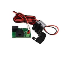
Ultra-Lightweight Rogowski Coil Current Probe


detailed image
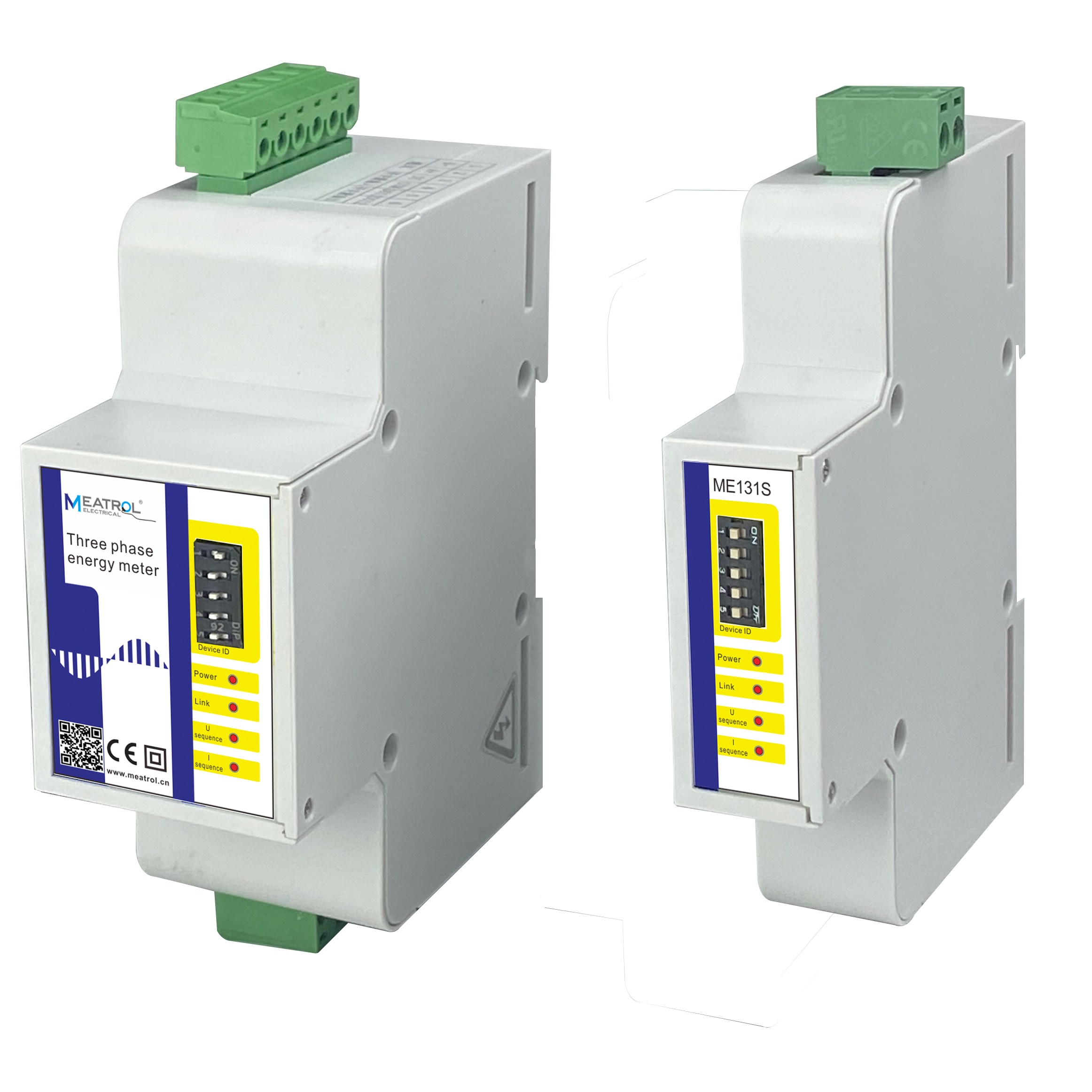
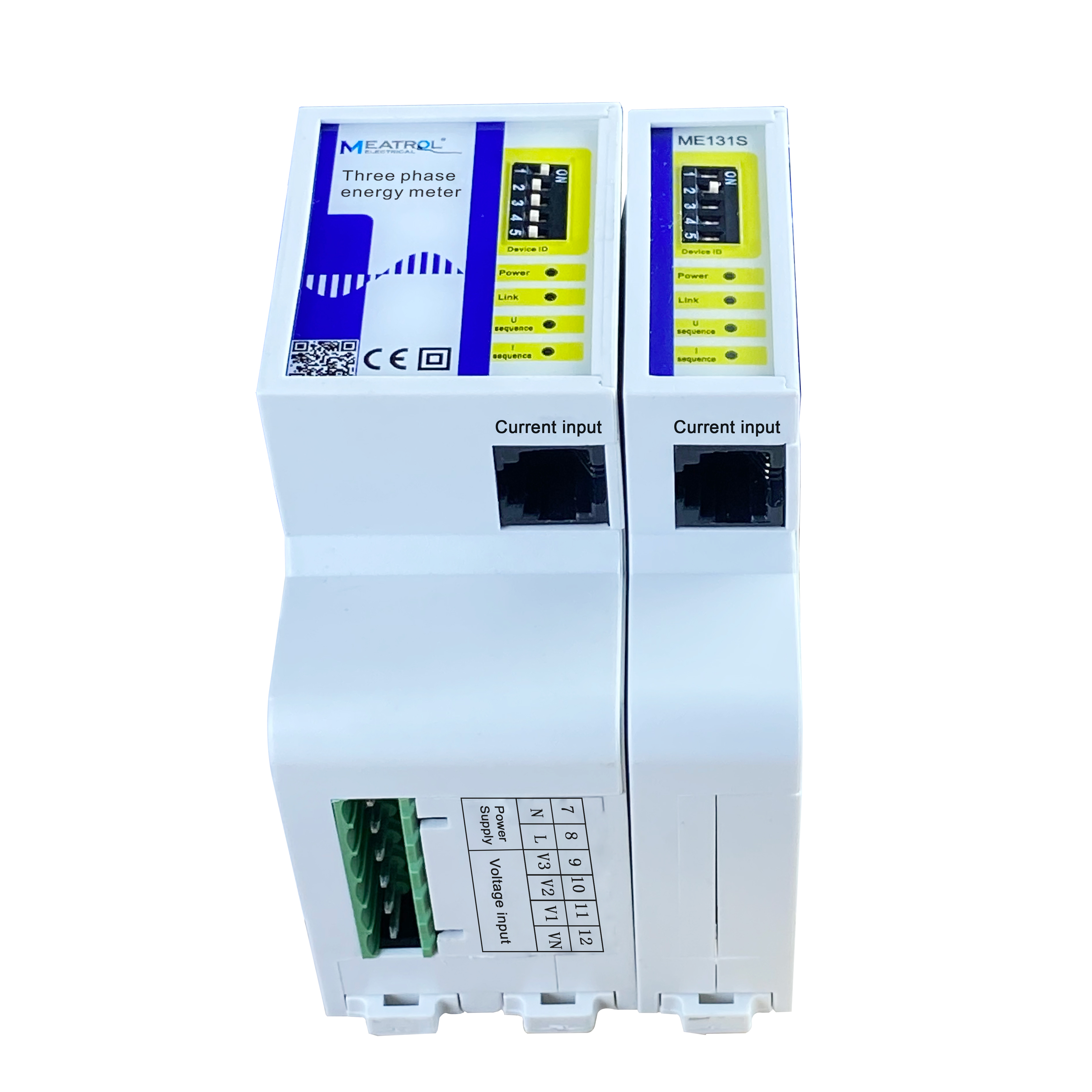
Main table: ME131M
Sub-table:ME131S
* Accuracy: 0.5S
* sensor:
* Accuracy: 0.5S
* sensor:
3-in-1 CT with RJ12 port
3-in-1 Rogowski coil sensor RJ12 port
* Monitor up to 32 circuits
(single phase/three phase)
*Host integrated power supply
* Monitor up to 32 circuits
(single phase/three phase)
*Host integrated power supply
Rice and Yami
* Communication: Modbus-RTU,
* Communication: Modbus-RTU,
RS485
* Maximum baud rate: 38.4 kbps
*Beta software
* Maximum baud rate: 38.4 kbps
*Beta software
Compact and space-saving
Plug design
Centralized installation
Easy maintenance
Excellent function
economic cost
Plug design
Centralized installation
Easy maintenance
Excellent function
economic cost
333mV current transformer:
5A: SCT-10, diameter 10mm
Rogowski coil current sensor:
100A: MRC-24 diameter 24mm
600A: MRC-36 diameter 36mm
1000A: NRC-100 diameter 100mm
3000A: NRC-150 diameter 150mm
6000A: NRC-200 diameter 200mm
VIEW MORE
YOU MAY LIKE